Hey smart home folks!
While looking around for a smart rgbw outdoor flood light, compatible with home assistant and no dependencies to a public cloud I came across this information regarding a not Tasmota compatible device:
https://templates.blakadder.com/unsupported/lumary_floodlight.html
As stated in the article, the built-in chip (Tuya CB2S ) isn’t compatible but it should be easy enough to replace it. So I ordered the flood light and some ESP-02S chips as replacement. Opening the enclosure was easy by removing seven screws and the electronics are wrapped by a shrink tubing:

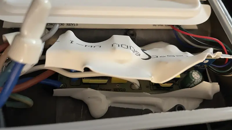
After cutting the shrink tube open with a knife, it was easy to remove the pcb with the CB2S chip on it.
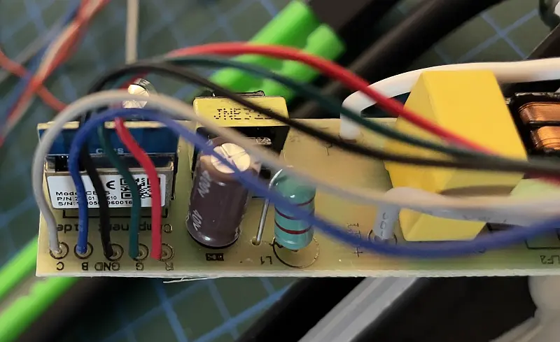
The wires that are going to the LEDs are color coded and on the pcb back it is easy to see to which pin the wire is connected.

Next step was to flash ESPHome to the new ESP-02S Chip. I used an ttl adapter and soldered the wires for flashing directly to the new chip. To get the ESP-02S into “flash mode” it is required to connect ground (GND) to Pin 1 (GPIO1). After connecting RX, TX, 3,3V and GND it is possible to write the Tasmota image or in my case the ESPHome image to the chip.
Important: Double check 3,3V because 5V will fry the ESP-02S!
I prepared an ESPHome Image in Home Assistant using the legacy format and the following config.

When using the config update all values in “<>”-Brackets to your needs.
substitutions:
  device_name: "<device-name>"
  friendly_name: "<Friendly Device Name>"
  description: "Lumary Smart Floodlight RGBW"

esphome:
  name: "${device_name}"
  comment: "${description}"
  platform: ESP8266
  board: esp01_1m

# Enable Home Assistant API
api:
  encryption:
    key: "<encryption key>"

ota:
  password: "<ota password>"

# Enable logging
logger:
  baud_rate: 0
  level: DEBUG

captive_portal:

web_server:
  port: 80

wifi:
  ssid: !secret wifi_ssid
  password: !secret wifi_password
  # Enable fallback hotspot (captive portal) in case wifi connection fails
  ap:
    ssid: "${device_name}"
    password: "<AP Pasword>"

# Sync time with Home Assistant
time:
  - platform: homeassistant
    id: homeassistant_time

output:
  - platform: esp8266_pwm
    pin: GPIO14
    frequency: 500 Hz
    id: pwm_output_white
  - platform: esp8266_pwm
    pin: GPIO13
    frequency: 500 Hz
    id: pwm_output_blue
  - platform: esp8266_pwm
    pin: GPIO5
    frequency: 500 Hz
    id: pwm_output_red
  - platform: esp8266_pwm
    pin: GPIO4
    frequency: 500 Hz
    id: pwm_output_green

# Configure RGBW Light
light:
  - platform: rgbw
    name: "${friendly_name}"
    color_interlock: true
    restore_mode: RESTORE_DEFAULT_ON
    red: pwm_output_red
    green: pwm_output_green
    blue: pwm_output_blue
    white: pwm_output_white
The following links helped me to build the config:
ESPHome PWM Output: https://esphome.io/components/output/esp8266_pwm.html
ESPHome RGBW Light: https://esphome.io/components/light/rgbw.html
After flashing the ESP-02S it was time to desolder the Tuya chip and replace it with the ESP-02S.

Then I placed the pcb back in the flood light enclosure and sealed the shrink tube with some hot glue.

Some moments after powering the flood light it shows up in Home Assistant and is controllable:


I hope this helps someone who is looking for an smart flood light compatible with ESPHome or Tasmota.
Adrian
Schreibe einen Kommentar